- Case Study 1: Coast Guard Boat Eagle
- Case Study 2: DRS Concentric Mast Cylinders
- Case Study 3: Trans FX Scene Element Structures for Universal Studios
- Case Study 4: Nammo M72FFE Shoulder Launch Projectile Failure Investigation
- Case Study 5: Eclipse Composite Satellite Ka Band Reflectors
- Case Study 6: Eclipse PPS Composite Reflector and Injection Mold Analysis
- Case Study 7: Design, Analysis, and Material Change for Steel Pressure Vessels
- Case Study 8 and 9: Armstrong Boeing 737 Radome Adapters
- Case Study 10: Armstrong Aerospace BirdStriker™
- Case Study 11: ATK LAS Test Bay Analysis
- Case Study 12: MSLASS Structural/Vibration and Fatigue Analyses
- Case Study 13: Nammo Missile Canister Drop Analysis
- Case Study 14: AGC/Bell Helicopter V280 Overwing Fairing
- Case Study 15: JWST XRCF Cryogenic Testing
Case Study 1: Coast Guard Eagle Illustrates the Reverse Engineering Capabilities at WCA
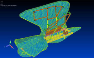
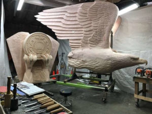
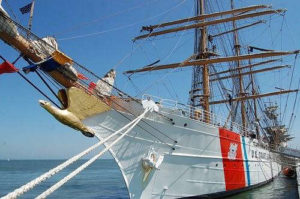
The current wooden bow Eagle figurehead is being replaced by a newly designed fiberglass (FG) composite structure. The composite skins and internal FG structure were designed by WCA using a Reverse Engineering technique of scaling photographs of the new Eagle sculpture. This technique allowed the construction of a Finite Element Model (FEM) verifying the Eagle’s structural integrity to withstand the bow/wave acceleration loading.
Due to the lager size of the Eagle (15ft x 10ft x 8ft) and the non visible bow attach points, the internal FG structure required multiple design integrations for manufacturability.
Case Study 2: Concentric Cylinder Project Illustrates the D&A and Manufacturing Knowledge at WCA
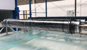
DRS was moving the manufacturing of several concentric carbon fiber cylinders, which comprised a telescoping mast, to a new manufacturer. During restart of the manufacturing, multiple technical design issues arose as the finished composite tubes were inspected. The root cause of these issues were determined by WCA to be:
1) Improver ply consolidation or compaction increasing void volume and machined surface delamination.
2) A non rotating mandrel during cure resulting in multiple composite tubes large cylindricity variations.
This analysis required a multi-week evaluation of the new manufacturers facility in Summer 2019. DRS is now in full scale production of these concentric tubes for their telescoping mast.
Case Study 3: Entertainment Structures Illustrates the Composite D&A Experience at WCA
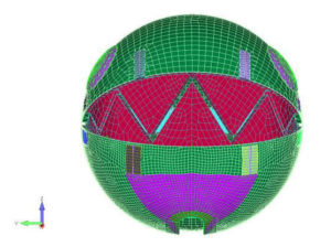
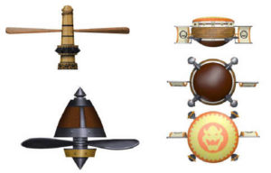

These large composite structures range in size from 7 feet in diameter, and heights up to 15 feet. The various structure rotate, fall and lunge at high speeds resulting in large lateral and rotational accelerations.
Since guests on the new ride will be in close proximity to the scene elements, Universal Studios required a high 5.0 factor of safety be incorporated in the Finite Element Analysis (FEA) and the calculation of the margins of safety. A total of six different scene elements were designed and analyzed using FEA with the laminate optimization to minimize the weight of the structures.
Universal Studios plans on the ride opening Fall 2020.
Case Study 4: Shoulder Launch Projectile Illustrates the Composite D&A and Manufacturing Experience
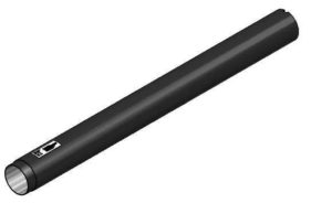
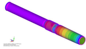
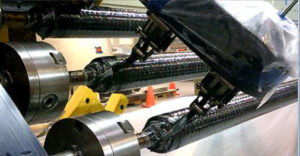
During the manufacture and acceptance testing of the composite cylinders, multiple cylinders failed proof testing. WCA coordinated the Failure Investigation for Nammo to determine if proof failures were due to a design and/or a manufacturing issue. FEA of the composite cylinder resulted negative margins of safety due to low fiber yield and strength. In addition, it was found that the winding machine was incorrectly set to produce an out of spec fiber/resin content.
WCA also analyzed the dynamic pressure loading of the cylinder, as the projectile exits, to predict the laminate hoop strain observed during live fire testing.
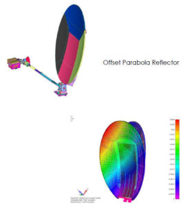 Case Study 5: Reflector Project Illustrates the D&A and Distortion Analysis Experience at WCA
These reflector projects involve the design and analysis of the composite/metallic structures under aerodynamic, thermal, and solar heating loads. The thermal/structural analysis is conducted to calculate structural margins of safety, as well as define the reflective surface RMS distortion to evaluate the signal db loss of the antenna.
Computation Fluid Dynamic (CFD) analysis of the multiple winding load pressure distributions are calculate through a collaboration with a Subcontractor. The convex and concave pressures distributions are applied to the FEM. An RMS comparison of the initial and distorted reflective surface is made to predicted the antenna signal loss due to aerodynamic and thermal loading.
WCA has successfully designed and developed 5 composite reflectors in production for our Client.
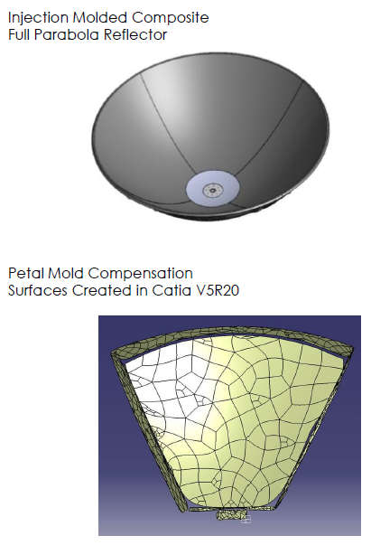 Case Study 6: Reflector Project Illustrates the Injection Mold Tooling Experience at WCA
WCA has been developing material properties and analyzing an innovative low cost injection molded Polyphenolic Sulfide (PPS) and chopped fiber composite reflector. A test matrix was developed to evaluate Tensile/Compression strengths and CTE. Thermal/structural was conducted to define RMS surface distortion.
As part of the mold tooling design, a mold surface compensation analysis was conducted using Catia V5R20. Base on the inspection of the As Built reflector petal, the mold injection tool surfaces were compensated to account for the uneven or variable part shrinkage. This was accomplished by importing the inspection point cloud, and creating new offset tooling surfaces. A compensated tool surface mold was created and the injection mold was re machined to the compensated surfaces.
Final petals injected have been inspected, and the injection mold now produces acceptable parts for the composite reflector.
Case Study 7: Project Shows the D&A and ASME Composite Code Change and Revision Experience
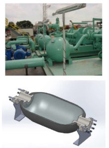 This project involves a paradigm shift for the Oil and Gas Industries to incorporate carbon composite materials and technologies into a market which solely relies upon steel. These pressure vessels operate at pressures of 10,000psi, while transferring viscous and corrosive drilling fluids at temperatures approaching 250 ⁰ F.
A pressure vessel design has been developed which takes advantage of the superior carbon hoop fiber strengths over steel, resulting in reduction of the 15,000 pound steel vessel to a composite vessel weighing 2,200 pounds. This weight savings of greater than 85% significantly reduces the transportation and handling costs for remote and off shore well sites. A patent is currently pending for this design.
Since these pressure vessels are regulated by the requirements of ASME Boiler and Pressure Vessel Code, Section X, two Code Case requests were submitted to allow the use of drilling fluids and an increase in the maximum operating temperature. These Code Case requests were approved by the ASME Section X Committee in late 2014.
Case Study 8 and 9: Radome Adapter Projects Illustrate the D&A and Test Validation Experience at WCA
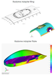 WCA has been evaluating the Thermal/Structural response of two types of Boeing 737 iDTV Radome Adapters. The Adapter Ring and Adapter Plates are subjected to multiple Aerodynamic, Thermal and Inertial environments during aircraft flight maneuvers.
An additional vibrational analysis is being conducted for the Adapter Ring to verify Boeing 737 random and engine out vibrational environments do not overload the Radome and Adapter Ring. A Boeing 737 fight test was conducted in April 2016, and a comparison analysis will be completed to verify the FEA is correctly predicting the component accelerations and strains.
WCA has been working with FAA Designated Engineering Representatives (DERs) to verify all loads, material properties, modeling techniques, and thermal/structural results are accurate and meet the stringent requirements for this commercial aircraft by the FAA. A Structural Type Certificate (STC) was issued, and the Adapter Ring is currently being installed on several aircraft.
Case Study 10: BirdStriker TM Project Demonstrates Composite Fatigue Analysis and Testing Experience at WCA
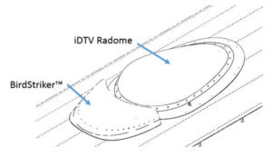
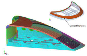
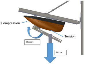
This project involved the structural finite element and fatigue analysis, plus testing of the composite BirdStriker TM for fight approval by the FAA on Boeing 737 aircraft. The structure was first analyzed for loading by multiple aerodynamic pressure distributions and thermal environments. In order to calculate the proper fastener loads in the structure, a contact surface modeling technique was utilized which accounted for the “heal toe” interaction of the composite structure and the aluminum fuselage base plate.
A fatigue analysis and test setup was then developed to cycle the BirdStriker TM to verify the structure is capable of withstanding 150,000 take off and landing cycles. The fatigue testing was successfully completed with FAA approval, and a Structural Type Certificate (STC) was issued.
Case Study 11: LAS Test Bay Tooling Analysis and Testing Experience at WCA
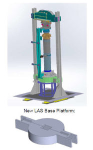 This project involved the structural analysis of the D5 Hydro Test Bay with the installation of the Launch Abort System (LAS) Chamber for structural testing. The finite
element analysis involved the modeling of LAS Chamber and Nozzle, plus the test bay columns, cross beam, and test bay floor.
The initial analysis of the test bay was to determine if the floor welds were capable of withstanding the increased loading required for LAS. The analysis showed that the test bay floor welds resulted in negative margins of safety. WCA worked with ATK to design a suspended base platform, which resulted in positive margins for the LAS test setup.
The LAS Structural/ Hydro Test was successfully completed in 2015 using the D5 Hydro Test Bay.
Case Study 12: MSLASS Armament Structure Demonstrates Vibrational Analysis Experience at WCA
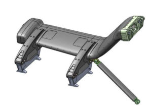 The Multi-Station Light Armament Support Structure (MSLASS) is an armament carrying wing attached the exterior of a Sikorsky UH 60 Black Hawk helicopter. The
MSLASS is capable of carrying multiple armament configurations.
WCA successful design and analyzed the composite structure to react the flight maneuver and landing loads. In addition to acceleration loading, a dynamic transient rotor blade vibration load was analyzed to insure attachment stresses were acceptable and the structure met its fatigue life requirements.
The FEM was successfully correlated to static deflection load testing. The dynamic and frequency response of the FEM was verified through a series of instrumented flight tests where flight maneuvers were conducted such that the dynamic rotor blades vibration environment was reacted into the MSLASS. Critical strains were measured in the fatigue limited structures and all models were correlated successfully to validate the fatigue life predictions.
12 Sets of MSLASS structures have been manufactured, and are currently flying.
Case Study 13: Missile Canister Impact Non Liner Analysis Experience at WCA
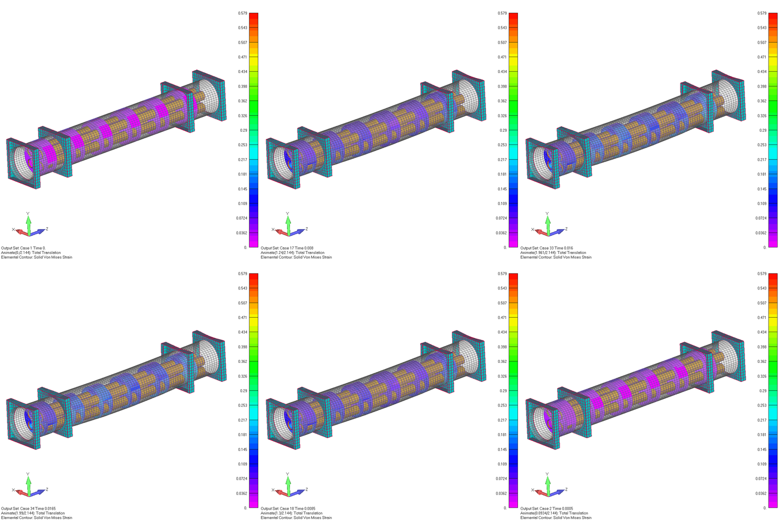 This project involved the assessment of the non-linear shock response of canister drop with four missiles. The canister was designed to minimize the acceleration induced into the missiles to be less than 100g’s.
In order to successfully complete these analysis, the dynamic shock response and modulus of the packaging foam was determined. Working with the University of Utah, foam impact tests were conducted. These tests defined the non linear foam modulus used in the FEM.
A successful canister design was developed which was predicted to result in a 64g load being induced into the missiles. Actual drop testing at a height of four feet confirmed the missiles saw a maximum acceleration of 65g. The analytical prediction was within 1.5% of the measured acceleration.
Case Study 14: Project Illustrate Honeycome Sandwich Composite D&A Experience at WCA
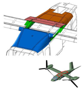 This project involved the structural finite element analysis of the composite fairings loaded by multiple aerodynamic pressure distributions. WCA developed the initial design concept, composite laminates, and fuselage integration structures. The design and analysis of the overwing fairings were successfully detail for a PDR review
with Bell Helicopter.
The composite laminates and honeycomb core layups and materials were optimized to meet operational aero load and crash acceleration requirements. Structural margins of safety were calculated for all components and interfaces.
This project required the development of Level 1 component product drawings of each fairing and fuselage integration structures. Manufacturing planning documents were generated to support the composite components tool design.
Case Study 15: Project Shows Distortion Analysis Experience with XRCF Cryogenic Testing
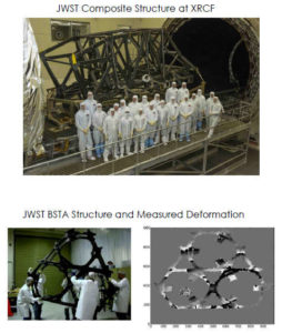 This project involved thermal distortion analysis of the NASA James Webb Space Telescope (JWST) composite Backplane Support Frame (BSF) for ATK. Finite element analysis was conducted on the structure to predict the distortion at 25 ⁰ Kelvin, and then compared to the measured distortion unit a laser system inside the XRCF. The laser system was capable of measuring nano meter displacement.
In preparation for the full scale BSF testing a three section subscale BSTA test article was also analyzed and the distortion was measured at 25 ⁰ Kelvin.
This key milestone was completed December 2013 to predict the distortion of the JWST Center Section/BSF structure at XRCF.